LED headlight failure is a common issue that affects night‑driving safety and can cause inspection failures. This article provides a systematic troubleshooting and repair guide – helping owners restore lighting quickly and cost‑effectively. From power connections to chip testing, from driver replacement to circuit repair – we cover each step in detail.
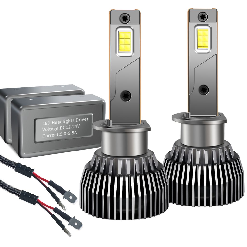
1. Understanding Key Specifications
LED lighting systems consist of power modules, control units, drivers, and LED chips. Configurations vary across models:
| Type | Voltage | Features |
|---|---|---|
| Standalone LED headlights | 12V or 24V | Dedicated driver |
| Integrated LED tail lights | Multi‑channel control | Dynamic turn signals |
| Ambient lighting | 5V or 12V | Multi‑colour adjustable |
Chip specs: most models use SMD LEDs – 0.5‑1W per chip – operating voltage 2.8‑3.2V. Knowing these parameters helps pinpoint faults.
2. Power Connection Checks
Power connections are the first thing to check:
- Fuse inspection: use a multimeter to check fuse continuity – normal resistance <0.5Ω. If blown, replace with the same rating (typically 5‑10A) and check for overload.
- Contact cleaning: use fine sandpaper to clean metal contacts – remove oxidation – ensure contact resistance <1Ω.
- Wiring inspection: check for loose plugs – use a pull test – inspect for damaged or aged wires (engine‑bay wiring is prone to heat‑damaged insulation).
3. Driver Fault Diagnosis
LED driver failure accounts for about 30% of LED faults.
Testing:
- Measure driver output voltage with a multimeter – normal: 12V±0.5V (12V system) or 24V±1V (24V system)
- If output is abnormal – check input voltage first
- If input is normal but output is abnormal – replace the driver
Notes:
- Integrated LED lamps: drivers are often built‑in – replacement must match the original interface
- CAN‑bus controlled smart drivers: require a diagnostic tool to read fault codes – common codes include “driver communication error” and “output voltage abnormal”
4. Chip Inspection and Repair
LED chip failure is the most common cause – accounting for about 40% of faults.
Inspection:
- Visual check: look for black spots, scorch marks, or cracks
- Multimeter diode test: forward voltage should read 0.6‑0.7V – reverse should show open circuit
Repair options:
- Single chip failure: temporary bypass – solder across the damaged chip’s pins – ensure smooth joints
- Over 30% chips damaged: replace the entire LED panel – avoid secondary failures from localised overheating
- Replacement matching: match colour temperature (typically 6000K‑6500K) and luminous flux (100‑150lm per chip)
5. Circuit System Diagnostics
Complex circuit issues require systematic checks:
| Test Item | Tool | Normal Range | Action if Abnormal |
|---|---|---|---|
| PWM signal | Oscilloscope | Duty cycle 10‑90% | Check control module |
| Switch output | Circuit tester | 0V (off) / 12V (on) | Check switch state |
| CAN bus | Diagnostic tool | Error‑free transmission | Check bus communication |
| Circuit resistance | Multimeter | <0.1Ω/m | Segment test to find break |
Broken wire repair: use heat‑shrink tubing and solder – ensure insulation and mechanical strength.
6. Cooling System Maintenance
Poor cooling is a major cause of premature failure – accounting for about 15% of faults.
Maintenance tips:
- Clean heatsinks: use a soft brush and compressed air – keep fin spacing >2mm
- Check cooling fans: measure fan motor resistance – normal range 5‑15Ω
- Replace thermal paste: if dry – reapply thermal conductivity ≥3.0W/m·K
- Allow cooling space: maintain at least 5mm air gap – avoid contact with plastic parts
7. Professional Repair Advice
If self‑diagnosis doesn’t resolve the issue:
- Choose a qualified shop: look for automotive electronics certification – request a detailed diagnosis report
- Check parts sources: OEM parts usually carry 1‑2 year warranty – aftermarket parts need compatibility testing
- Smart system matching: use original diagnostic equipment for programming – avoid missing functions
- Post‑repair road test:
- Low‑beam height: at 10m – light centre height should be 0.7‑0.8H (H = lamp centre height)
- High beam: should reach at least 100m
Quick Fault Distribution Reference
| Fault Type | Share | Main Diagnostic Method |
|---|---|---|
| Chip damage | 40% | Visual + multimeter diode test |
| Driver failure | 30% | Multimeter output voltage check |
| Poor cooling | 15% | Clean heatsink – check fan |
| Power/wiring issues | 10% | Fuse check – wiring inspection |
| Other | 5% | Professional diagnostic tool |